555 Timer Schematic / 555 Timer Wizard Multisim Help National Instruments - Additional • timing from microseconds through hours terminals are provided for triggering or resetting if • operates in both astable and monostable modes desired.
byAdmin-
0
555 Timer Schematic / 555 Timer Wizard Multisim Help National Instruments - Additional • timing from microseconds through hours terminals are provided for triggering or resetting if • operates in both astable and monostable modes desired.. The 555 timer can be obtained very cheaply from pretty much any electronic retailer. This pin connects to the negative side of the battery. The values of r1 and c1 determine how long the output will remain high. There are simple circuits for beginners and advanced engineers. 555 ic timer block diagram 555 ic timer block diagram.
This pin connects to the negative side of the battery. A monostable 555 timer is required to produce a time delay within a circuit. Here is the practical demonstration of the bistable mode of 555 timer ic, where we have connected a led to the output of the 555 ic. Derivatives provide two or four timing circuits in one package.it was commercialized in 1972 by signetics. A collection of 555 circuits using the 555 timer as an astable oscillator with different duty cycles.
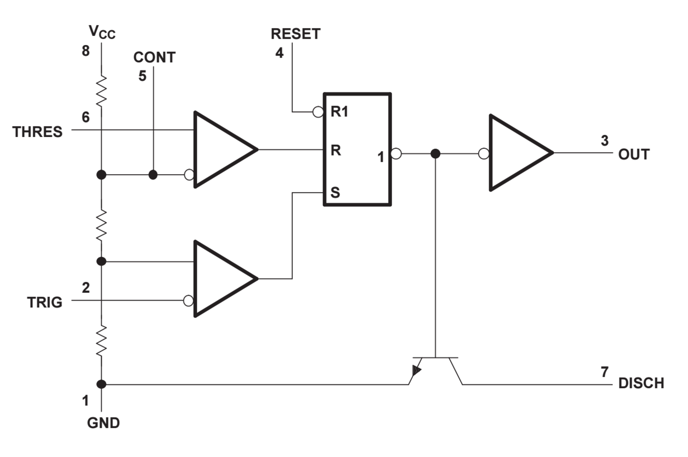
Building A Drsstc Pt 15 The Interrupter Pt 2 Electronics Forum Circuits Projects And Microcontrollers from www.rfwireless-world.com The block diagram of a 555 timer is shown in the above figure. 555 timer is an industrial standard ic existing from early days of ic. The 555 can be used to provide time delays, as an oscillator, and as a flip flop element. Additional • timing from microseconds through hours terminals are provided for triggering or resetting if • operates in both astable and monostable modes desired. 555 timer ic is an integrated circuit used in a variety of timer, pulse generation circuit, and oscillator circuit applications. If a 10uf timing capacitor is used, calculate the value of the resistor required to produce a minimum output time delay of 500ms. For a great resource on the 555 timer, opamps, and other ic's check out the engineer's mini notebook: The ic can operate in three different modes such as astable, monotstable and bistable, because of which it can be adapted into many types of circuit designs like time delay circuits, pulse generation circuit, oscillator circuit and much more.
It has been redesigned, improved, and reconfigured in many ways, yet the.
Daman shah june 5, 2021. Various light actuator and relay driver circuits are also further enclosed. The circuits explained here are 10 best small timer circuits using the versatile chip ic 555, which generates predetermined time intervals in response to momentary input triggers. Resistive network consists of three equal resistors and acts as a voltage divider. The 555 timer can be obtained very cheaply from pretty much any electronic retailer. If you want to know all the pinout of the 555 timer, what each pin is and what each pin does, see 555 timer pinout. The working modes of a 555 timer are astable, bistable, and monostable. 500ms is the same as saying 0.5s so by rearranging the formula above, we get the calculated value for the resistor, r as: This led will be switched on when button s1 is pressed and switched off when button s2 is pressed. Unlike the monostable mode and astable modes, bistable mode doesn't need a resistor and capacitor to set the timing of the circuit. The 555 integrated circuit is the most popular chip ever manufactured. This pin connects to the negative side of the battery. Jetzt timer 555 angebote durchstöbern & online kaufen.
The 555 timer delay before turn on circuit we will build is shown below. These on off intervals can be adjusted by varying the 555 timer output and number of counter outputs. Simple 555 timer circuits & projects. We have a large collection of simple and advanced projects using 555 timer ic. 555 timer was first introduced by signetics corporation in 1971 as se555/ne555.
Leap 328 from leap.tardate.com Lm555 timer 1 features 3 description the lm555 is a highly stable device for generating 1• direct replacement for se555/ne555 accurate time delays or oscillation. The 555 timer is a simple integrated circuit that can be used to make many different electronic circuits. The values of r1 and c1 determine how long the output will remain high. The output voltage from the chip is around 1.5 v lower than vcc when high and around 0 v when low. Various light actuator and relay driver circuits are also further enclosed. We have seen in the last few tutorials that the 555 timer can be configured with externally connected components as multivibrators, oscillators and timers, with timing intervals ranging from a few microseconds to many hours. A monostable 555 timer is required to produce a time delay within a circuit. For a great resource on the 555 timer, opamps, and other ic's check out the engineer's mini notebook:
Basic 555 monostable multivibrator circuit.
The 555 timer ic is an integrated circuit (chip) used in a variety of timer, delay, pulse generation, and oscillator applications. If a 10uf timing capacitor is used, calculate the value of the resistor required to produce a minimum output time delay of 500ms. For a great resource on the 555 timer, opamps, and other ic's check out the engineer's mini notebook: Derivatives provide two or four timing circuits in one package.it was commercialized in 1972 by signetics. We have seen in the last few tutorials that the 555 timer can be configured with externally connected components as multivibrators, oscillators and timers, with timing intervals ranging from a few microseconds to many hours. Let us discuss in detail about this circuit. These on off intervals can be adjusted by varying the 555 timer output and number of counter outputs. Figure 1 is the pinout and functional block diagram for the 555 timer ic. In this project, we are using 555 timer ic to create various timer circuit like 1 min timer circuit, 5 min timer circuit, 10 min timer circuit, and 15 min timer circuit. There are simple circuits for beginners and advanced engineers. The ic can operate in three different modes such as astable, monotstable and bistable, because of which it can be adapted into many types of circuit designs like time delay circuits, pulse generation circuit, oscillator circuit and much more. The 555 ic timer circuit above shows a very straightforward design where the ic 555 forms the central controlling part of the circuit. The 555 can be used to provide time delays, as an oscillator, and as a flip flop element.
Referring to the timing diagram in figure 3, a low voltage pulse applied to the trigger input (pin 2) causes the output voltage at pin 3 to go from low to high. Once this switch is pushed, the circuit pulls its output to a. Additional • timing from microseconds through hours terminals are provided for triggering or resetting if • operates in both astable and monostable modes desired. In this category, we have handpicked some really useful 555 timer circuits which will be interesting to electronics engineering students and hobbyists alike. Working modes of 555 timer ic.
555 Timer Tutorial The Monostable Multivibrator from www.electronics-tutorials.ws Independently manufactured by more than 10 manufacturers, still in current production, and almost 40 years old, this little circuit has withstood the test of time. This led will be switched on when button s1 is pressed and switched off when button s2 is pressed. This circuit uses very basic components like 555 timer and 4017 counter. From our earlier discussions we know that for a 555 in the delay timer mode, the delay could be accurately managed through a single external resistor and one capacitor. The output voltage from the chip is around 1.5 v lower than vcc when high and around 0 v when low. Being an integral part of electronics project, 555 timer ic is very often used in simple to complex electronics projects. Unlike the monostable mode and astable modes, bistable mode doesn't need a resistor and capacitor to set the timing of the circuit. The values of r1 and c1 determine how long the output will remain high.
This pin connects to the negative side of the battery.
In this project, we are using 555 timer ic to create various timer circuit like 1 min timer circuit, 5 min timer circuit, 10 min timer circuit, and 15 min timer circuit. 555 timer circuits (133) browse through a total of 133 555 timer circuits and projects including the timer's datasheet. We have seen in the last few tutorials that the 555 timer can be configured with externally connected components as multivibrators, oscillators and timers, with timing intervals ranging from a few microseconds to many hours. If you want to know all the pinout of the 555 timer, what each pin is and what each pin does, see 555 timer pinout. Lm555 timer 1 features 3 description the lm555 is a highly stable device for generating 1• direct replacement for se555/ne555 accurate time delays or oscillation. In this category, we have handpicked some really useful 555 timer circuits which will be interesting to electronics engineering students and hobbyists alike. This led will be switched on when button s1 is pressed and switched off when button s2 is pressed. Independently manufactured by more than 10 manufacturers, still in current production, and almost 40 years old, this little circuit has withstood the test of time. There are simple circuits for beginners and advanced engineers. Its name is derived from three 5k ohm resistors ,connected in series used in it.the timer ic can produce required waveform accurately. It has been redesigned, improved, and reconfigured in many ways, yet the. Figure 2 shows the basic 555 timer monostable circuit. The 555 timer can be obtained very cheaply from pretty much any electronic retailer.